First ever Restoration - Suffolk Super Colt - Lots of questions!
Hello all, I've been browsing the site more and more recently - mainly from search results while googling for information. After giving up cycling recently due to health problems i needed something to help pass the time and something to fettle with! I've always carried out servicing and repairs on my own cars and bikes, learning along the way and reading up about things i didn't know how to do, and like to think I’m mechanically competent.
There has always been something about engines that has intrigued me, and so i decided to see if I could strip down and refurbish a lawnmower. One came up nearby on the bay, a 'Suffolk Colt' which was advertised as spares / repairs due to 'No Spark - suspected coil'. I figured it was worth a punt and would be a good learning experience even if i can't manage to get it running. Looking online, Colt's didn't seem to quite match the look of my mower, which led me to discover it's actually a 'Super Colt'.
What started off as a simple 'Let's find out why it's not sparking' quickly resulted into a complete strip down of the entire mower and lastly the engine!! Taking plenty of pictures along the way, and bagging up nuts and bolts with labels so as not to forget what went where, I've now stripped the entire thing down so that I'm left with the engine block, and an exhaust that is well and truly welded to the block - thankfully it doesn't appear damaged, just rusty, so It can stay where it is (frustratingly for my OCD).
I'm going to test the waters here to make sure I can upload pictures properly, and once I can, I'll post up a few pictures I've taken during the strip down. I've come across quite a few things I’d really appreciate some advice with so anyone interested in looking/reading can hopefully help me out - which I’m hoping will help others out in future who are thinking of tackling the same sort of project.
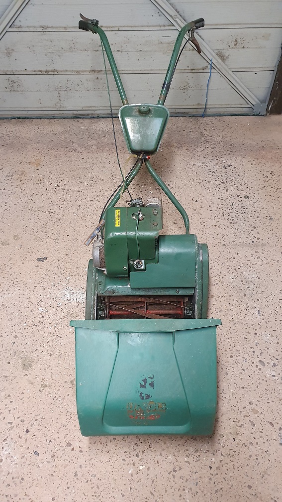
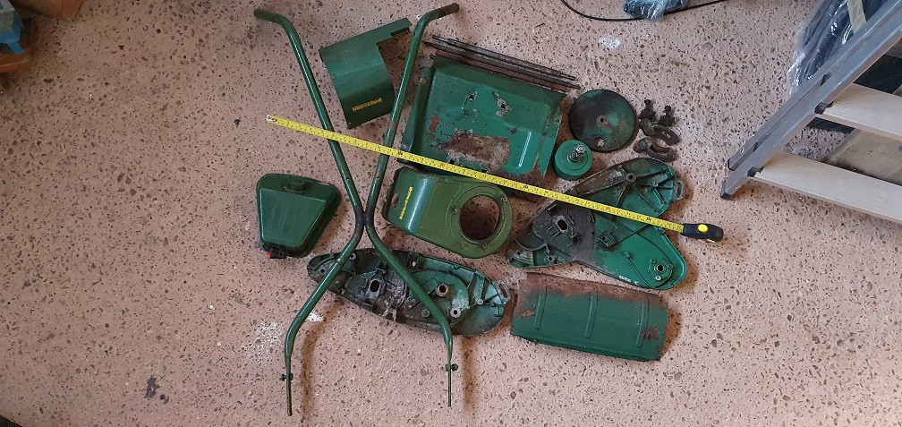
Here is a Picture of the mower after collecting it
Forums
The plastic plunger type, I
The plastic plunger type, I might have one, will have a look later. They don't seem too popular new now.
It might be a better idea just to use a cheap lever fuel tap to plug while derusting in case of a bolt with the wrong thread, I think the generic lever taps are about £3.
Brass Ewarts style plunger & body would be a few bob new I think and not original to that tank?
To plug -
2nd hand tank with tap would be cheaper ![]()
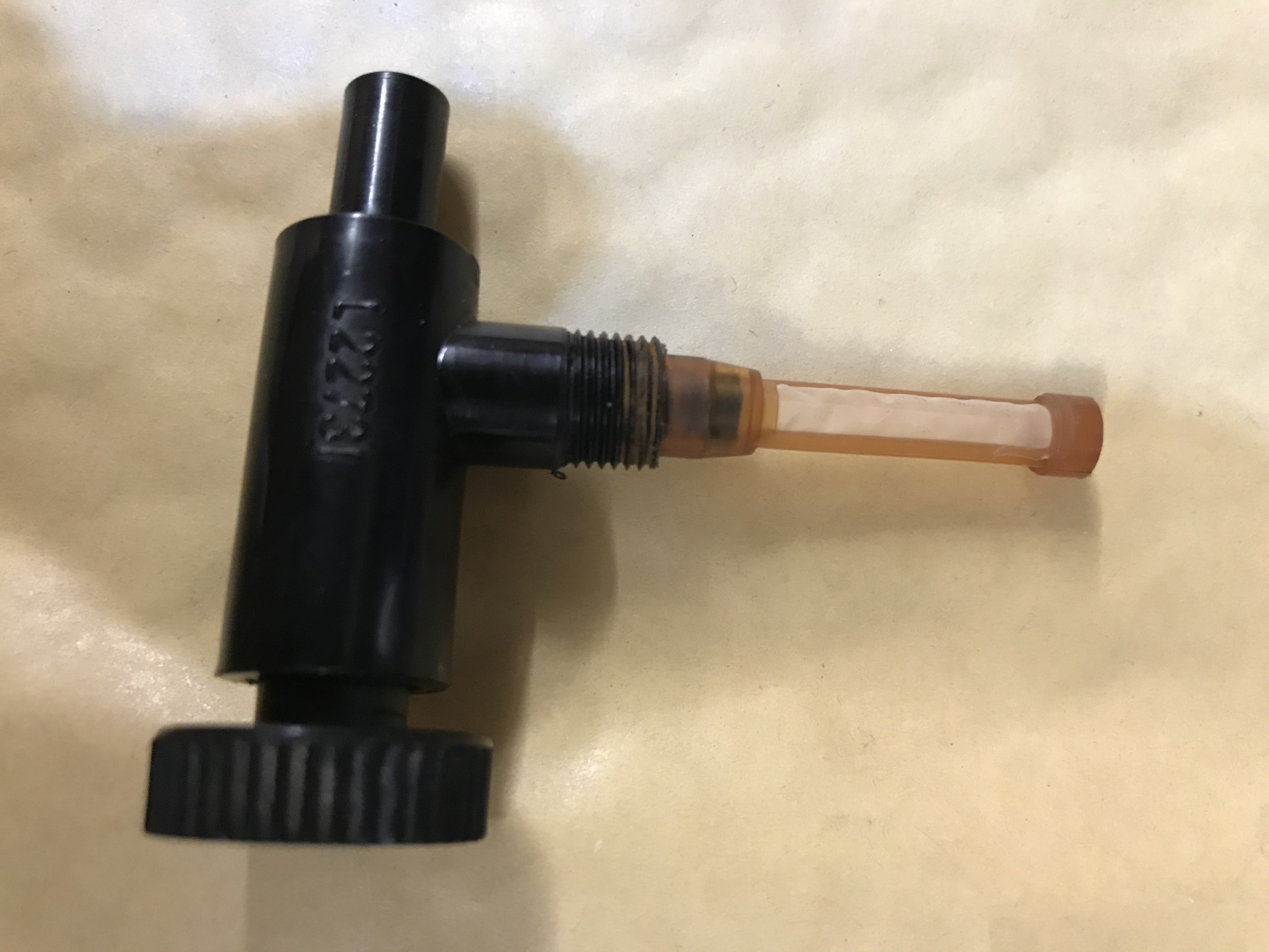
3/8" BSP (fine) code L22731.
3/8" BSP (fine) code L22731.
If you don't get any luck you can have this one.
Brilliant thanks Chris! I
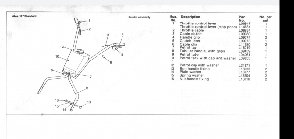
Brilliant thanks Chris! I couldnt see that part number when looking at the Atco standard manual, or the Suffolk super colt manual - I found L16019 and E8382

It seems most places are out
It seems most places are out of stock though, so I'll drop you a message about the tap ![]()
just sat and read all of this
just sat and read all of this, brilliant attention to detail and some great images
good luck with the rest
steve
Hi Steve, thanks very much,
Hi Steve, thanks very much, appreciate that. It feels like I'm getting much closer to being able to fire the engine up and hopefully get it running well. That's the next goal, before I get stuck in to the rest of the mower....
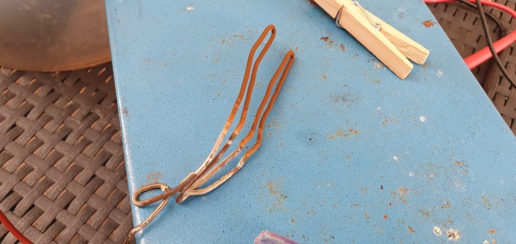
Had a good result with the
Had a good result with the electrolysis and the petrol tank. Using some sodium carbonate with water inside the tank, and a reshaped metal coat hanger - which was tricky to bend into the right shape so that it would go down into the tank and then around deep enough, but without touching the sides. Took a bit of trial and error, and a couple of blown fuses, but after constantly checking there was no continuity between the -ve and +ve , I managed to leave it running for a few hours, fizzing away, changing the coat hanger out half way through due to the rust build up


The subject has been covered
The subject has been covered on this forum several times in the past.
Its not actually necessary to construct a shaped electrode as electrolysis works on a "line of sight" basis but it is necessary to to avoid shorting out - as you found out.
https://www.oldlawnmowerclub.co.uk/forum/history-and-technical/technical/electrolysis-rust-removal
I had seen this covered and
I had seen this covered and read the various posts about it on the forum, and was also aware of the 'line of sight' principal for electrolysis. The reason I bent the electrode round like that was because of the angle of entry on my particular tank. If I used a straight electrode, it would barely be in the solution before hitting the back wall of the tank. I needed more surface area of anode submerged in the solution, which is the reason for the shape I used. Other shaped fuel tanks may well be easier to achieve the same results with a straight electrode.
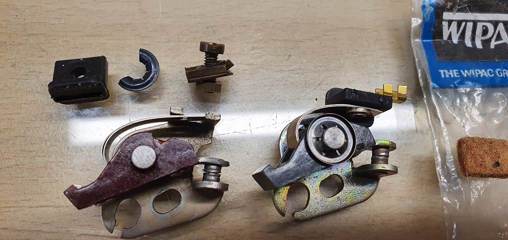
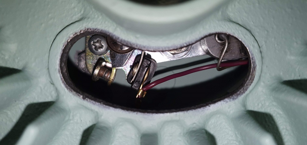
Back to the ignition points.
Back to the ignition points. I couldn't get the 2 surfaces to meet square no matter how I tried with a points file, and getting frustrated I tried to dismantle the points to attempt to dress each face separately. This resulted in a broken set of points, which is no surprise given the age of them and my frustration. A reminder to go slowly and the fact that not everything can or should be taken apart!
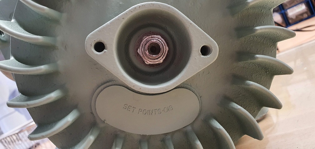
I sourced some new Wipac points online and set about fitting them in preparation for setting the gap to 0.018" and then setting the ignition timing
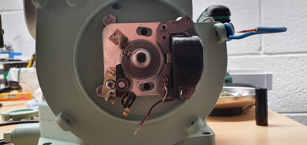
I used my DMM which has a buzzer function for continuity, attaching one probe to the engine casing and the other to the moving side of the points so that I could hear exactly when the points started to open
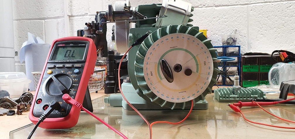
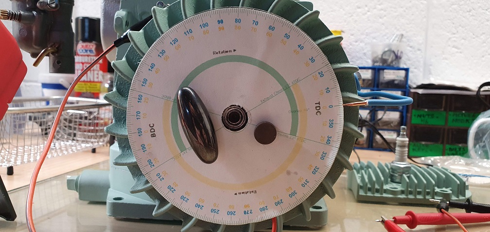
Printed off the timing wheel from a website and stuck it to an old CD, attached it to the face of the flywheel using a couple of magnets, and attached some copper wire to one of the screws on the engine casing which would act as a pointer.
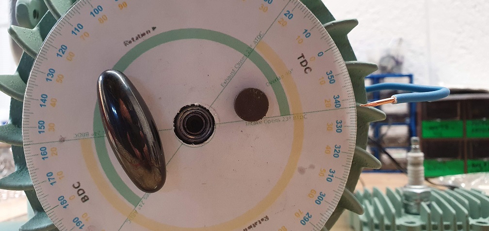
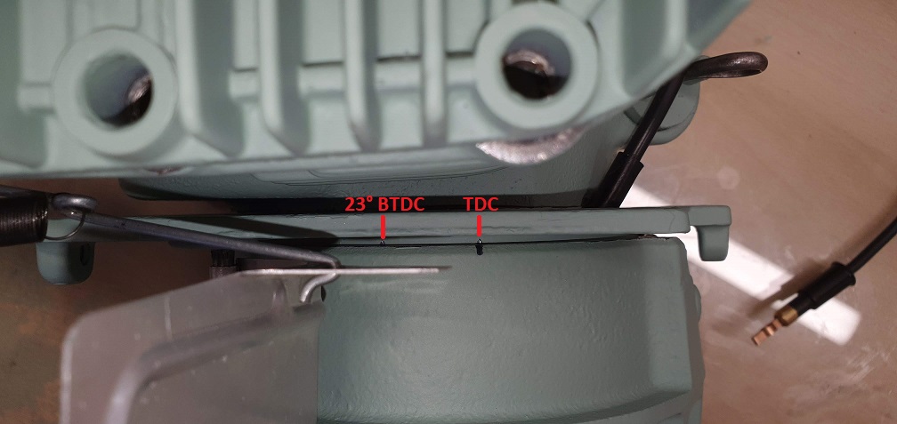
Having never set timing before on anything, I found a few videos online which helped explain it. With the engine head still off, it was easy to find TDC, so I marked this position on the flywheel and the backplate. Then turned the flywheel backwards until the points opened and the buzzer stopped, and checked the timing wheel to see how many degrees before the piston reached TDC that the points started to open. It showed 25°, so I removed the flywheel and loosened the 2 bolts holding the stator plate in place and rotated it clockwise very slightly and re-tightened the 2 bolts.
The points now started to open 23° before TDC. Double checked the points gap again just to be sure and then tightened everything up.
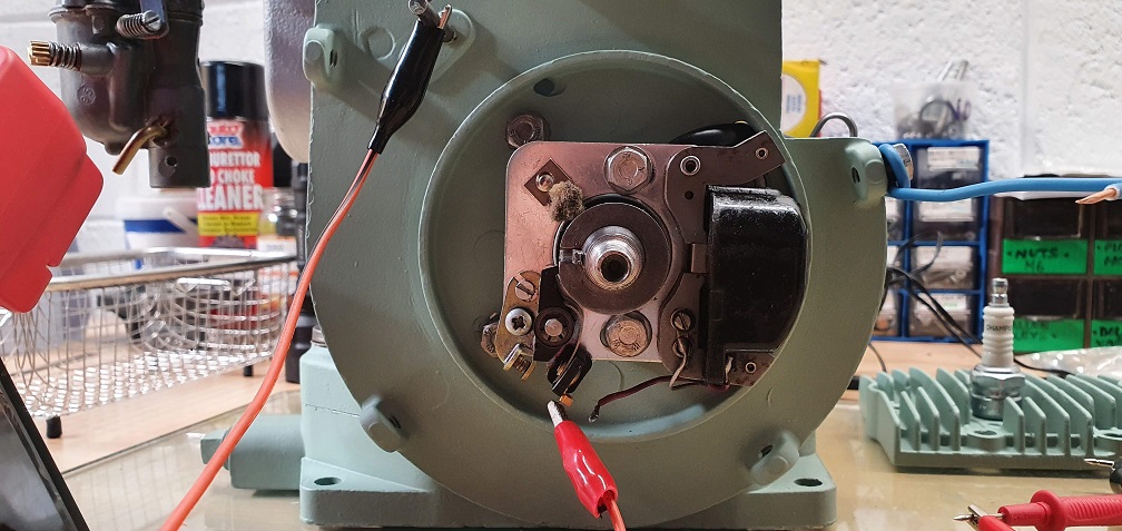
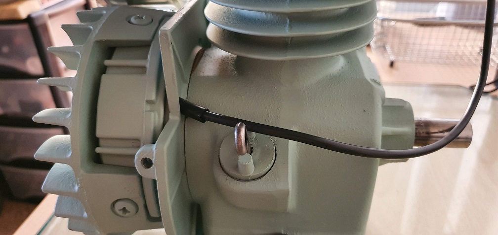
As the new points have a slightly different way of attaching the coil grounding wire compared with my original points, I folded one of the sets of prongs down onto the wires insulation and soldered the end of the wire to the tab, and folded the second pair of prongs down onto it.

I fitted a new length of HT lead my screwing it down into the coil where there is a small screw thread down inside the black casing, and then attached the protective sheath and fed the lead up through the backplate
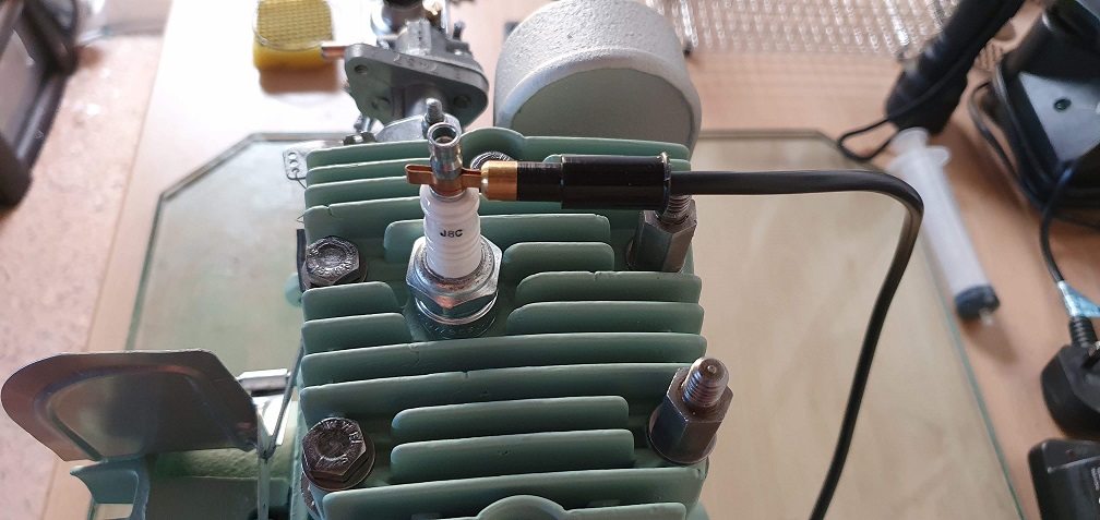
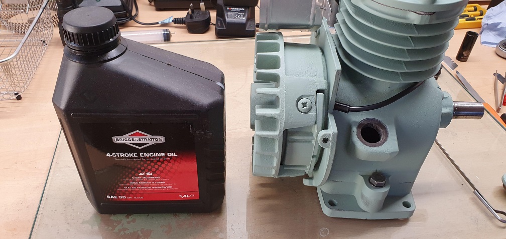
Put in 1/2 pint of SAE30 oil
Just by turning the flywheel by hand I was over the moon to discover that I now have a great spark being produced!!! Considering there was no spark at all before the strip down I've chuffed that this is now resolved.
The next thing will be to knock up a temporary engine stand to mount the engine to as well as the fuel tank, fit the correct fuel tap that Chris kindly helped me out with (thanks again!) and set the carb up ready to try starting it.......
You must be very near firing
You must be very near firing up now ![]()
Any particular reason why you are not going to reassemble and fire up the engine fitted ?
The next thing will be to
The next thing will be to knock up a temporary engine stand to mount the engine to as well as the fuel tank, fit the correct fuel tap that Chris kindly helped me out with (thanks again!) and set the carb up ready to try starting it.......
Do you have a Workmate? I have a vintage one that was marketed by the original designer, Ron Hickman, before he sold out to B&D. Ron also designed the original Lotus Elan.
I have made some quick change fixings to take the majority of domestic and light commercial lawnmower engines that come my way; the latest being one for a 7HP vertical shaft Tecumseh from a John Deere ride-on.
The reason I'm not mounting
The reason I'm not mounting the engine on the actual mower is that the rest of it is still in pieces, awaiting some form of blasting, then possibly either powder coating or priming and painting
As for a workmate, I had to throw one out a few months back as it was very old and had unfortunately suffered a lot of rust from being in storage some time ago - typical, as that would have been ideal for this sort of thing. They seem to come up cheap now and again so will keep a look out.
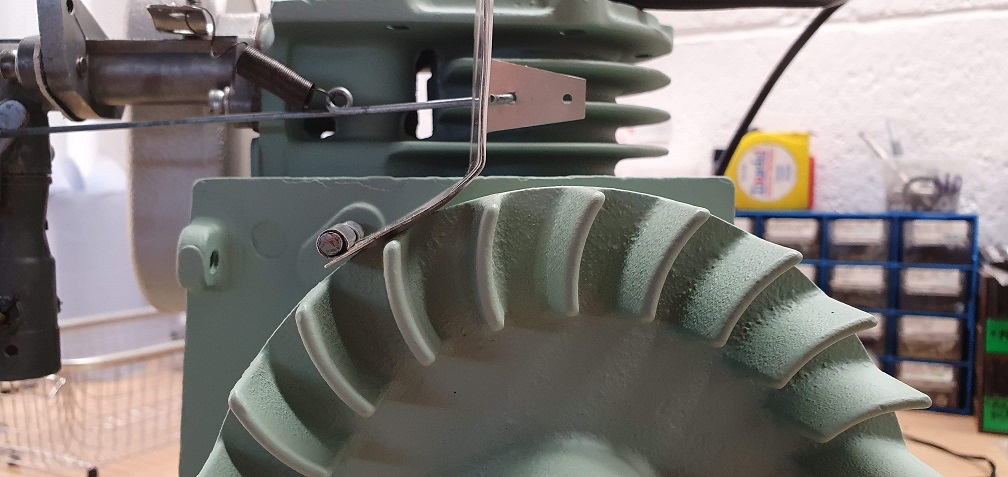
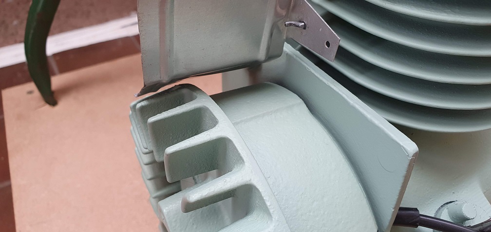
One question I wanted to ask was regarding the governor air vane. Am I correct in thinking that it should NOT be touching the flywheel at standstill? Currently it does on my engine, and I am wondering if this is because the spring has stretched at the end slightly so isn't providing any tension on the rod at all at rest?
Definitely should not. From
Definitely should not. From memory there were four different governor rods to cater for different manifold setups, so theres a possibility of a mix and match issue. Try flattening the angle of the vane a bit .
I have seen various manifold
I have seen various manifold designs/lengths so there could well be a mismatch with my manifold and rod.. I have adjusted the vane carefully to allow a little space between it and the flywheel when at rest
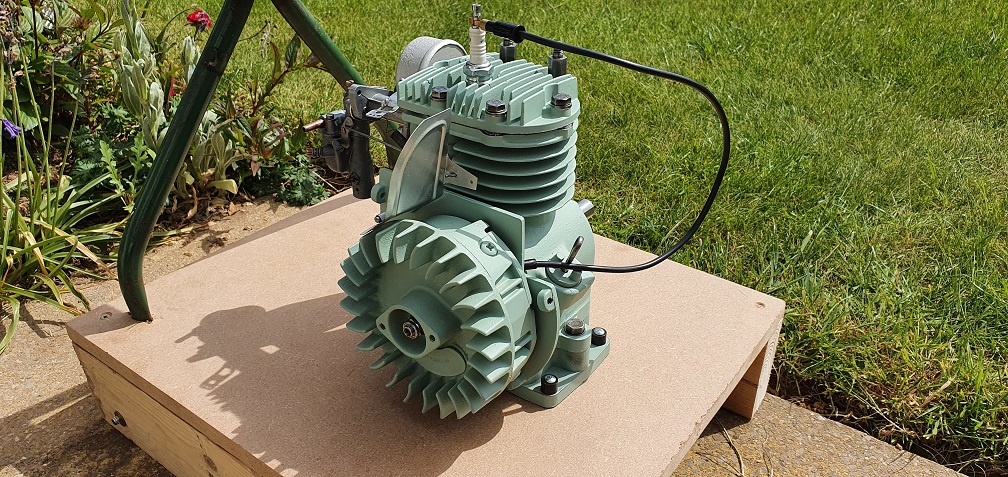
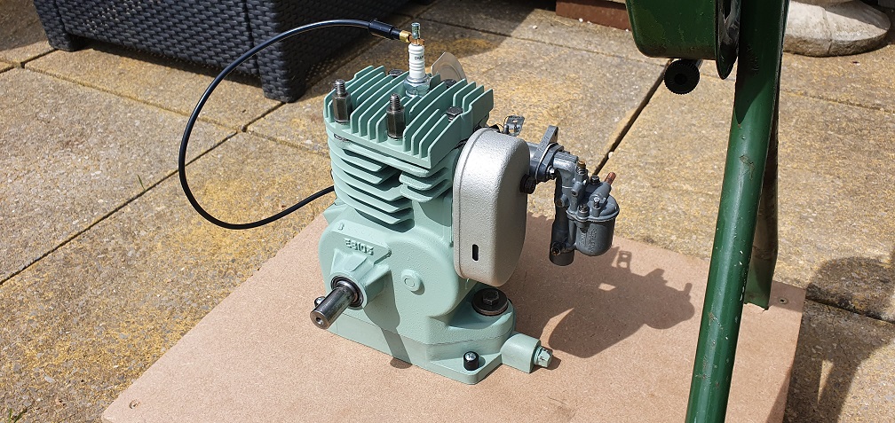
Also created my temporary engine stand so that I can use the petrol tank and engine together until the rest of the mower has been restored. Just awaiting the fuel hose to connect the tap to the carb inlet, and also waiting for the parts back from sandblasting, so that I can mount the recoil starter to the engine cowl and try and fire it up! I'll also fit the throttle cable and lever like it should be
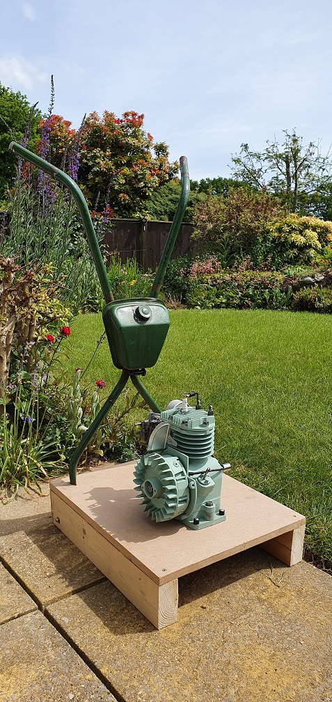
Very elaborate , I just hang
Very elaborate , I just hang a fuel tank from a nail in the shelf above .
You could put four wheels on it and push it back and forth while making engine noises ![]()
Sorry ![]() It’s been a long day doing battle with an Auto Certes that looked fairly tidy from a distance but actually had something amiss where ever one looked. Keeping the owner updated that his auction purchase is not quite the bargain that he thought is harder work than the greasy hand bit.
It’s been a long day doing battle with an Auto Certes that looked fairly tidy from a distance but actually had something amiss where ever one looked. Keeping the owner updated that his auction purchase is not quite the bargain that he thought is harder work than the greasy hand bit.
Not a bad suggestion that, I
Not a bad suggestion that, I'm sure I can find some wheels to put on it. It might look a bit silly without painting it green though. I'm sure I can mount the cutting cylinder for effect too. Yes, lockdown is taking its toll on me....
Hit a minor snag with the fuel hose. The carb inlet is 6.3mm and the petrol tap outlet is 7.7mm. Got hold of some 5mm internal diameter clear hose, which fits nicely over the carb inlet, but will not stretch over the fuel tap outlet. Perhaps 6mm hose will stretch enough without being too loose on the carb end....
Hot water or the hot air gun
Hot water or the hot air gun works wonders!
Looks like you have the later black fuel tap with the larger spigot . The earlier tap,usually with the red plunger, will match the carb inlet.
Thanks Angus - after trying
Thanks Angus - after trying both hot water and hot air, sadly the 5mm ID hose just won't stretch over the spigot. Way back on post #7 you kindly supplied a picture showing the fuel tap with the red plunger - is this one that you own and if so, are you able to give me the part number from it if it has one on the body? I wonder if its the same part number L22731 as the black tap that Chris helped me out with but just an earlier version? Or perhaps it has one of the two part numbers that I found when trying to locate the correct tap - L16019 or E8382?
That's a shame it's not a
That's a shame it's not a direct fit Scott. I would be tempted to try 6mm ID fuel pipe over 5mm if the carb inlet is 6.3. Would be a much better chance to get it to fit over the tap OD with some hot air wafting and if a snug fit at 6mm on the carb inlet, unlikely to back up and leak, although you could clamp it if concerned. A further bodge alternative is a reducing connector = https://www.ebay.co.uk/itm/5X-6-mm-to-7-mm-Straight-Reducing-Hose-Pipe-Tube-Connectors-for-GM-Ford-AMC/223738980409?hash=item3417e1e839:g:HDsAAOSwF~1dw7zO loads of these for pennies around. You know I'm not a purist ![]()
Thanks Chris - exactly my
Thanks Chris - exactly my thoughts - 6mm hose should be here in a couple of days and with some heat and gentle persuasion I'm hopeful it will just fit over the tap. My first thought was a reducing coupler, but would like to avoid if at all possible, although ti would be an easy solution! Given the difference in size between the tap and carb connectors I figured there must be some sort of mismatch, but as any plunger taps at all seem extremely hard to come by, I'm determined to make good use of this one!
The rest of the mower parts are currently with the blasters so not much more I can do until the hose arrives, and even then, I need to wait for the engine cowl to come back so I can fit the recoil starter to it and try firing the beast up! Then I'll be priming, painting and reassembling the rest of it, if I can remember how it all goes together....
Come on you guys, stop al
Come on you guys, stop all this mm business . It’s an Imperial Mower, from when we still had a bit of an Empire, and imperial taps and pipes all fit !
I even use an imperial fuel
I even use an imperial fuel can - an old jerry can......the garage fuel pumps gives me some very funny numbers when I fill it up...and not just the money value!
![]()
Tony
I even use an imperial fuel
I even use an imperial fuel can - an old jerry can......the garage fuel pumps gives me some very funny numbers when I fill it up...and not just the money value!M
If it’s a genuine Jerry can it will have a nominal 20 litre capacity. If the American version 5.3 US gallons.
Hardly Imperial !
Will promise to try harder,
Will promise to try harder, but I do struggle ![]()
American version 5.3 US gallons
Point in case, can't even agree on a standard gallon!
Yes guilty as charged - it's
Yes guilty as charged - it's easy to slip into modern units when trying to obtain some imperial size parts is getting harder and harder, and you are faced with a barage of metric sizes when searching the interweb. So given the size of the carb inlet I would think 1/4" hose would have been used, with the relevant red plunger tap. Can anyone recommend a supplier or type of hose that would be suitable? From what I've read standard PVC hose shouldn't be used with Petrol, and one should use something like trademarked 'Tygon' or similar which is resistant to fuels/oils. Clear hose would be preferable to allow easy visual of the fuel flow should there be any issues. What have others used?
I think that the Tyson type
I think that the Tygon type has greater ethanol resistance but my supply of standard clear tube in 3/16” and 1/4” id seems to be coping ok with the current level .
Scott, maybe over thinking it
Scott, maybe over thinking it - drum role please.... 1/4" internal clear mower fuel line, goes over 5/16"? barbed connection fine with a good push, tiny bit of red rubber grease if resisting. Had it on my go to 43 for ages nor problems. Can't remember where I got it, might have even been the mower centre. Let me know how much you need and can pop it in the post.
This if it loads...
This if it loads...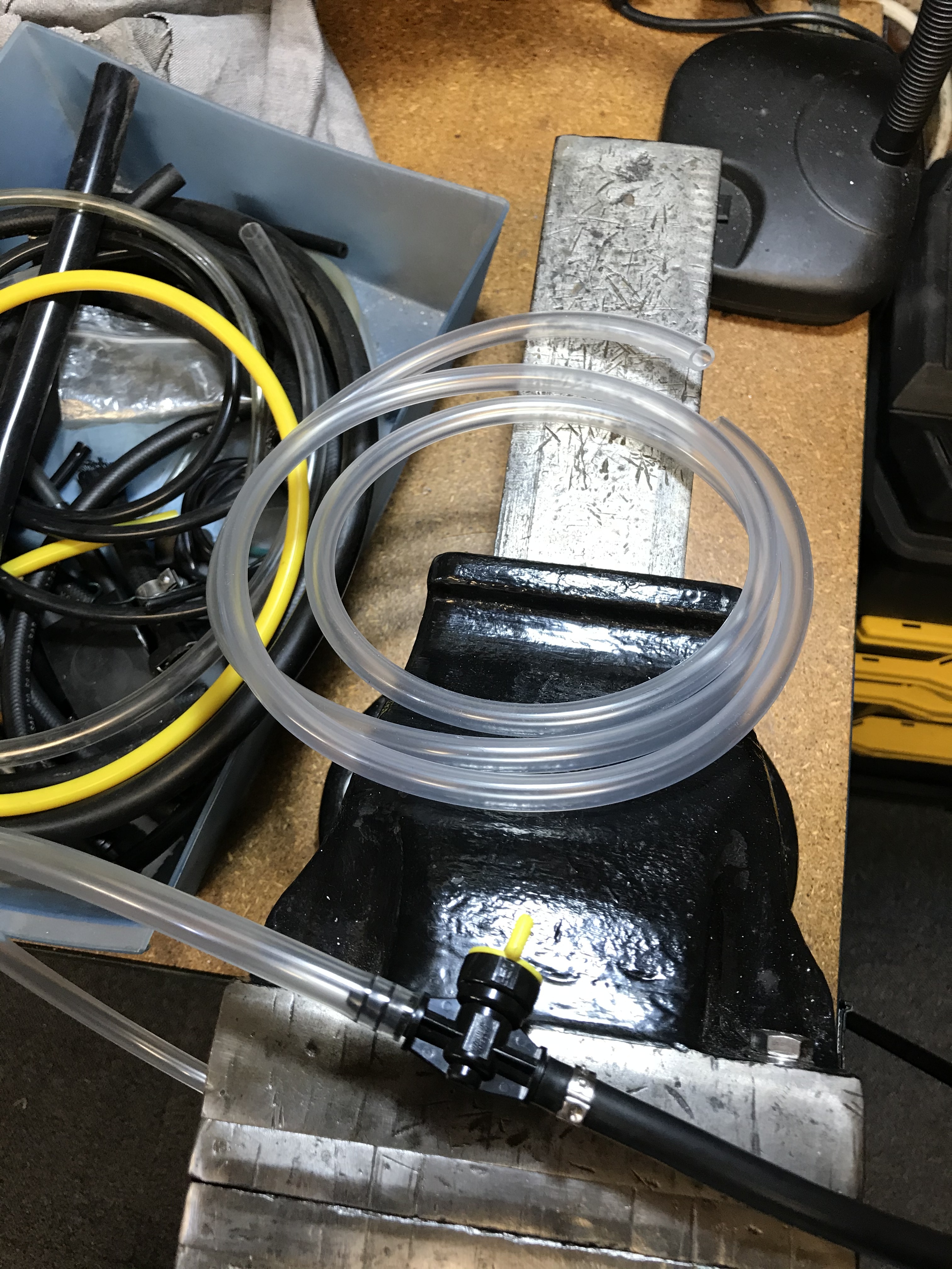
Thanks Chris, I'll see what
Thanks Chris, I'll see what the hose is like that turns up from my previous order and if no good, I'll give you a shout.
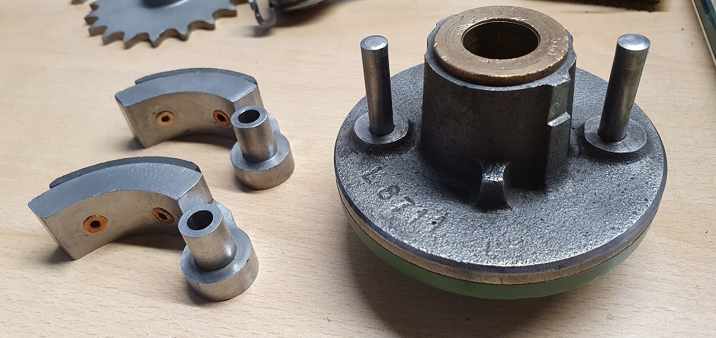
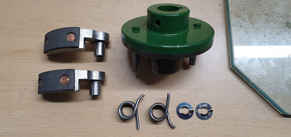
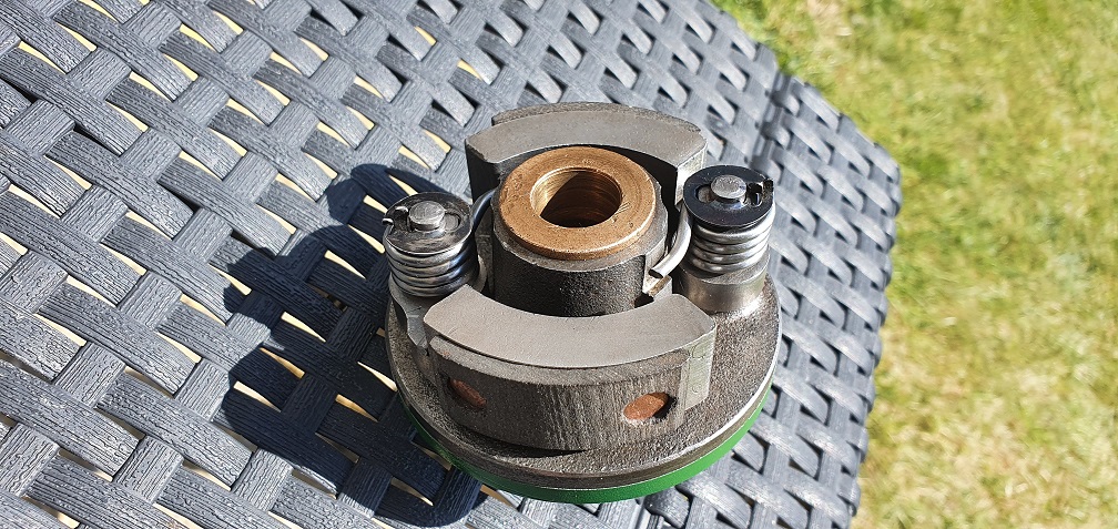
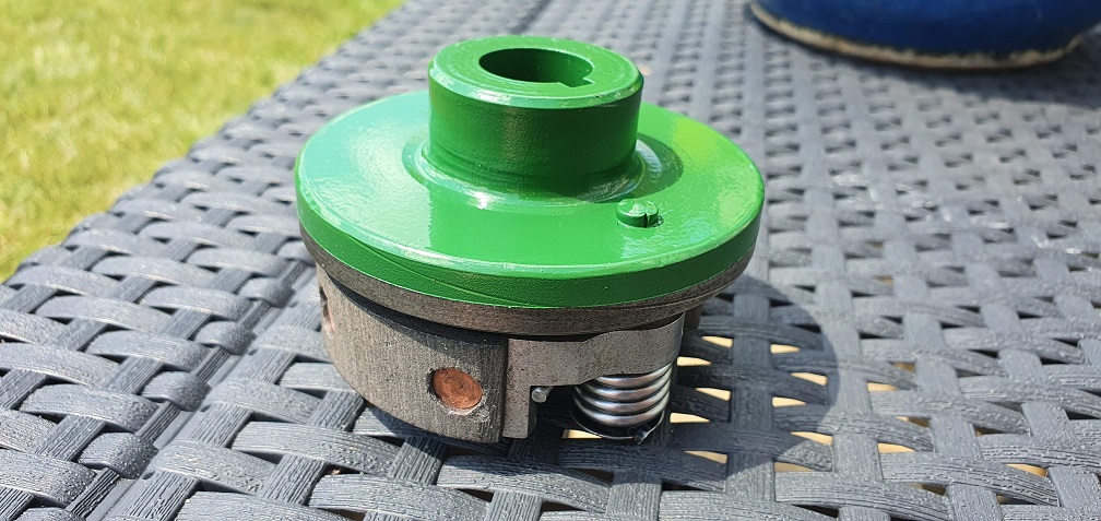
Meanwhile, I have tested out the RAL 6002 paint on my first part after priming - the clutch. Pretty happy with the colour match with the paint under the mower handles, which appears to be the original paintwork with bare metal underneath it. Once sprayed I was finally able to rebuild the clutch
Hi Red Leader, just wanted to
Hi Red Leader, just wanted to let you know I’m really enjoying your restoration thread - I’m a newbie to this and appreciate the detailed pics and commentary - looking forward to seeing more progress, Arthur
That’s the smartest Suffolk
That’s the smartest Suffolk clutch that I’ve seen in years!
It actually raises a question. Suffolk designed those clutches with the free ends of the shoes leading and the pivoted end trailing . Ransomes, do the opposite, and anyone one who has inadvertently fitted the shoes the wrong way round on a Marquis will be made aware of their error by a horribly snatchy take up . May be the smaller diameter of the Suffolk clutch reduces any tendency for the shoes to grab.
Hi Red Leader, just wanted to
Hi Red Leader, just wanted to let you know I’m really enjoying your restoration thread - I’m a newbie to this and appreciate the detailed pics and commentary - looking forward to seeing more progress, Arthur
Hello Arthur, glad you are enjoying the thread. If it provides useful information and help for fellow newbies then that's great!
That’s the smartest Suffolk clutch that I’ve seen in years!
It actually raises a question. Suffolk designed those clutches with the free ends of the shoes leading and the pivoted end trailing . Ransomes, do the opposite, and anyone one who has inadvertently fitted the shoes the wrong way round on a Marquis will be made aware of their error by a horribly snatchy take up . May be the smaller diameter of the Suffolk clutch reduces any tendency for the shoes to grab.
Thanks Angus, very happy with how the clutch turned out. I had to look up some pictures of Marquis clutches to see what you meant, and can see that they are considerably larger than the suffolk. Perhaps the smaller surface area of the friction material does help prevent it from being too grabby on the suffolk...

Just a thought re the Suffolk
Just a thought re the Suffolk / Ransomes clutches, could it be that the combination of shorter clutch shoes on the Suffolk clutches so less centrifugal effect and comparatively stronger spring rates has an effect on the way that the drive is taken up.
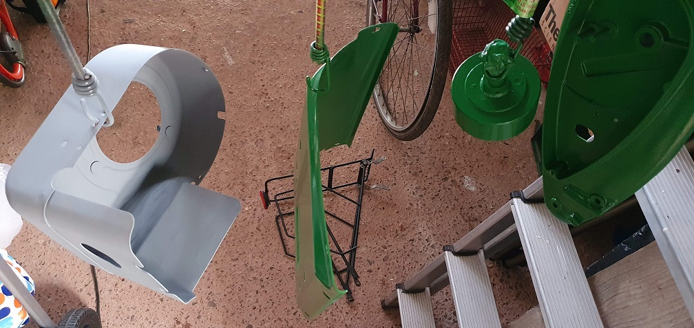
Clutch ponderings aside, a
Clutch ponderings aside, a few updates on the restoration. The parts are back from the sandblasters. 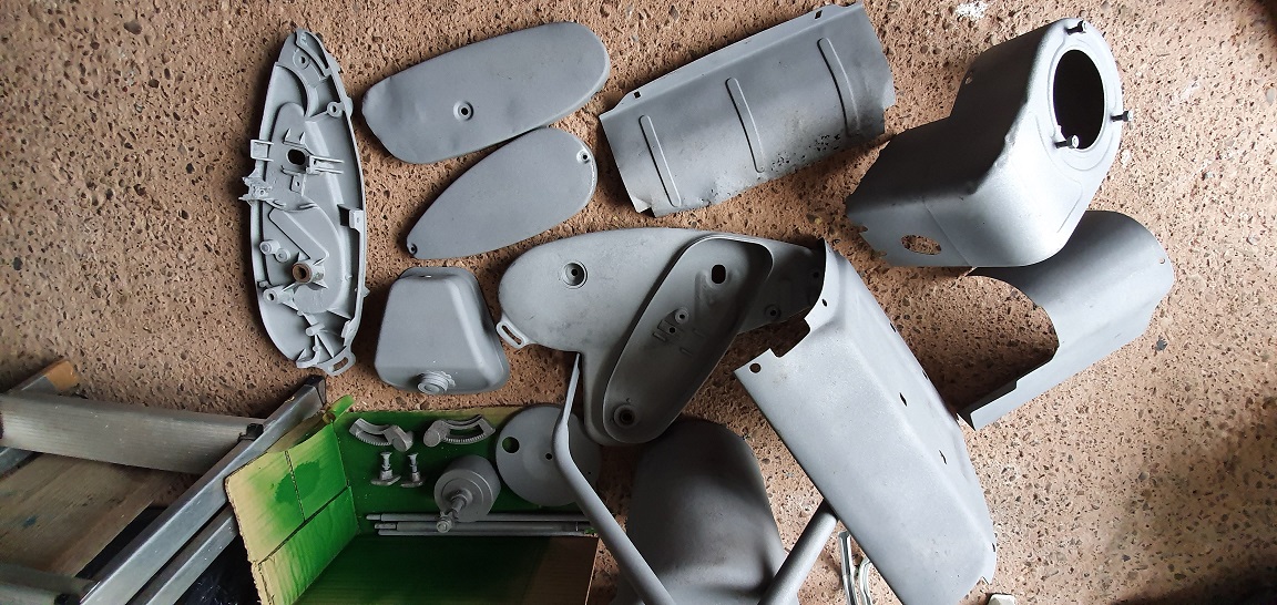
From other restorations I've looked at, it seems the general consensus is to leave the rear roller unpainted. Would it be worth perhaps treating it / sealing it with something?
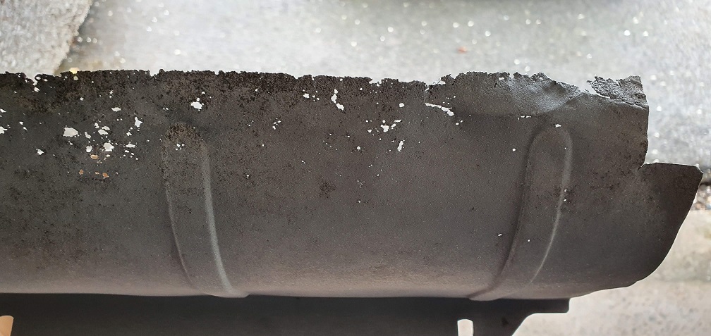
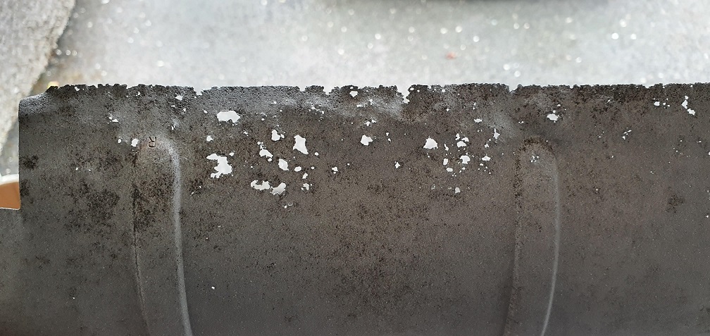
I knew the grass throw plate was a little worse for wear with rust, however I'm not sure if i should just treat the metal, prime paint and leave it as it? Structurally the majority of it is sill there so will do it's job fine I suspect, and might be difficult finding one in better condition?

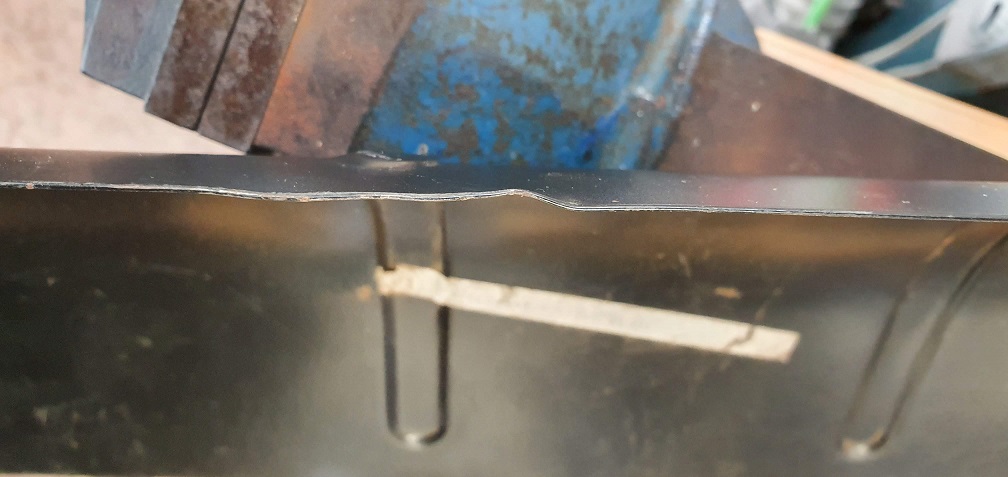
There is also considerable damage to one of the side panels
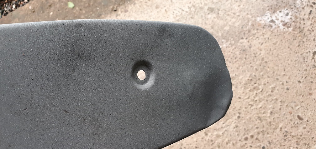
This would require a fair bit of work to put straight (as far as I know with limited metalwork knowledge) which would be beyond my tools/skills/capability so perhaps worth just looking for a replacement in better condition.......
Oh dear!
Oh dear!

Angus's words sprang to mind
Angus's words sprang to mind when seeing the side cover and the deflector...
I would also look for a replacement for the deflector plate, it is see-through now almost going to stealth mode. I looked around on ebay and this one looks better:
The side cover is even easier on ebay, a couple look a lot better then your original.
Thanks Henno, yes similar
Thanks Henno, yes similar words went through my mind, although I won't repeat them here...
Definitely replacing both items - like you say, the grass deflector really is going into stealth mode from the current Swiss cheese mode and more will no doubt disintegrate after the first blade of freshly cut grass hits it.
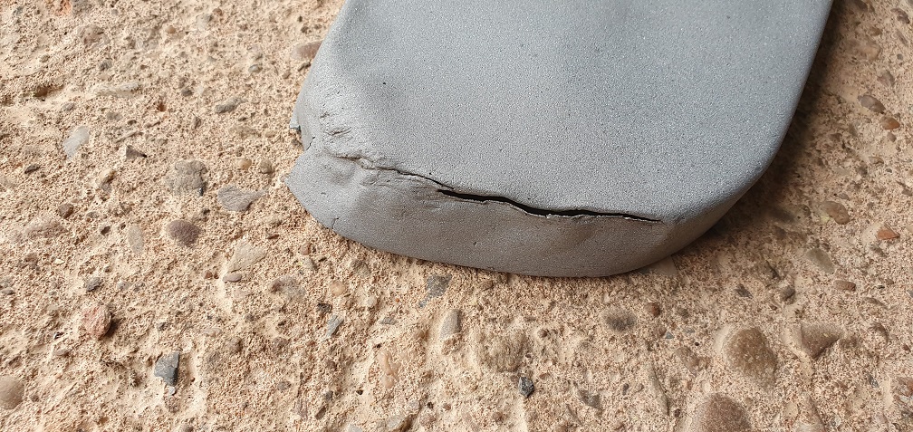
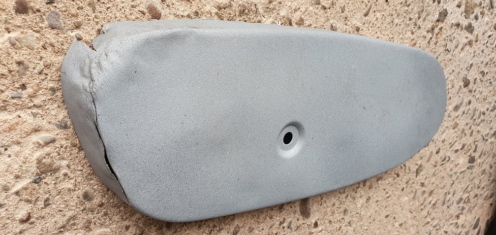
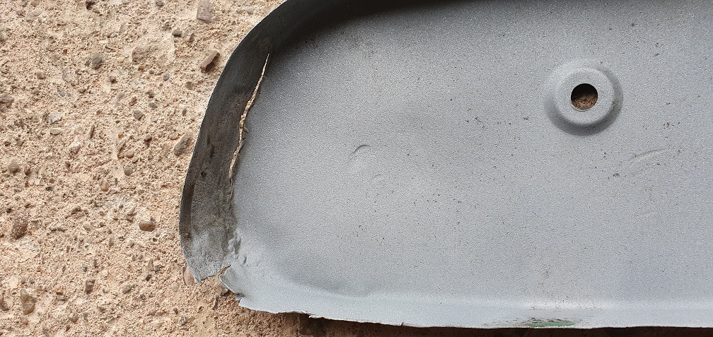
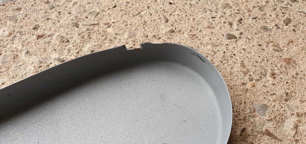
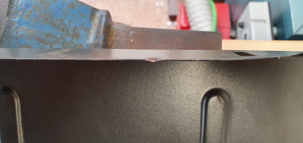
The chain case cover on these mowers does seem to have a tendency to split in that corner and suffer dents, from several that I've seen on ebay. I would have thought that residual oil from oiling of the chain would have gathered down there and protected against rust, however being so close to the ground, perhaps its more external impact damage from stones/curbing etc rather than rust damage?
There are a couple of each on ebay that are certainly much better than my items (thanks for the link Henno) so I will see about getting replacements ordered.
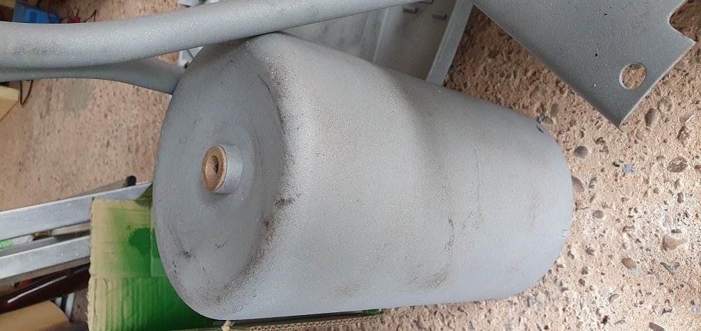
In the meantime, any thoughts on what to do with the real roller in terms of coating/sealing with something, or just leave it to weather naturally?
That's a setback on the
That's a setback on the panels...Per Henno best to try and source something better off ebay etc, I had a bunch of those side covers that I gave away, they had suffered similar but nowhere near as bad. Re the roller, I would agree with not painting if it's to be a working mower. Now the roller has been blasted it's going to take a while for the iron colour to come back, you could get it to flash rust back with phosphoric acid or similar, sand then treat with linseed wipe if you wanted to speed up the process.
On the deflector, I made one from stainless, see down this post. -> https://www.oldlawnmowerclub.co.uk/forum/history-and-technical/technical/yet-another-suffolk-punch-43-build-hopefully But noted at the time they were available new from Ransomes spares for £24, I've also patched a Marquis one, but again nowhere near that poor condition.
Edit - the Ransomes spares defector is for the 35 and out of stock until the end of the month anyway.. ->https://www.ransomspares.co.uk/parts/lawnmowers/suffolk-punch/deflector-plate/501927.htm
Edit - the Ransomes spares
Edit - the Ransomes spares defector is for the 35 and out of stock until the end of the month anyway.. ->https://www.ransomspares.co.uk/parts/lawnmowers/suffolk-punch/deflector-plate/501927.htm
By the look of it the one illustrated is for the later QX machines.
Thanks for all the info there
Thanks for all the info there Chris, appreciated.
Yes that 35 deflector is a little different to my one, with different mounting holes - however I used the part number L8447, or rather the newer F016L08447 number and found this one
https://www.ghsp.co.uk/f016l08447-concave---shop-soilded-atco-qualcast-bosch-fb005-8618-p.asp
I've asked for additional photos as it looks like there may be 2 extra mounting holes at the far end just out of the picture, which my plate doesn't have - neither do some I've found on ebay. Failing that, a decent condition one off ebay will do the job.
That stainless one you made looked very smart indeed Chris!
https://www.ghsp.co.uk
https://www.ghsp.co.uk/f016l08447-concave---shop-soilded-atco-qualcast-…
That is the pattern for your machine.
Thanks Angus, the grass
Thanks Angus, the grass delivery plate has been ordered, so just on the lookout for a decent chain case now.
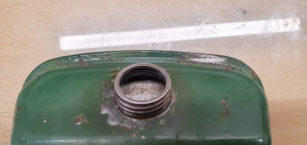
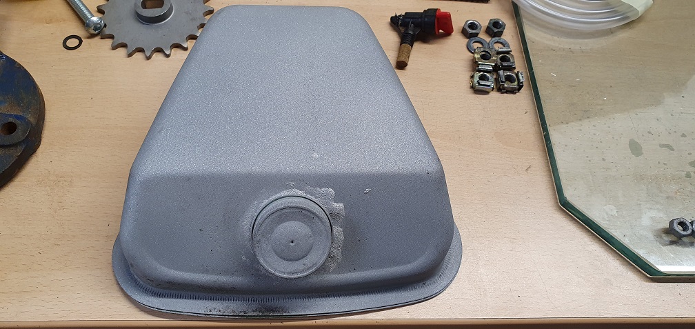
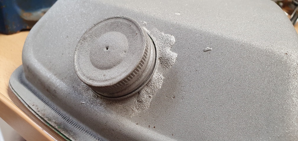
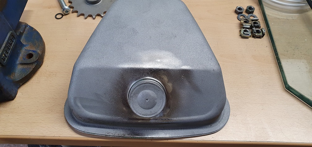
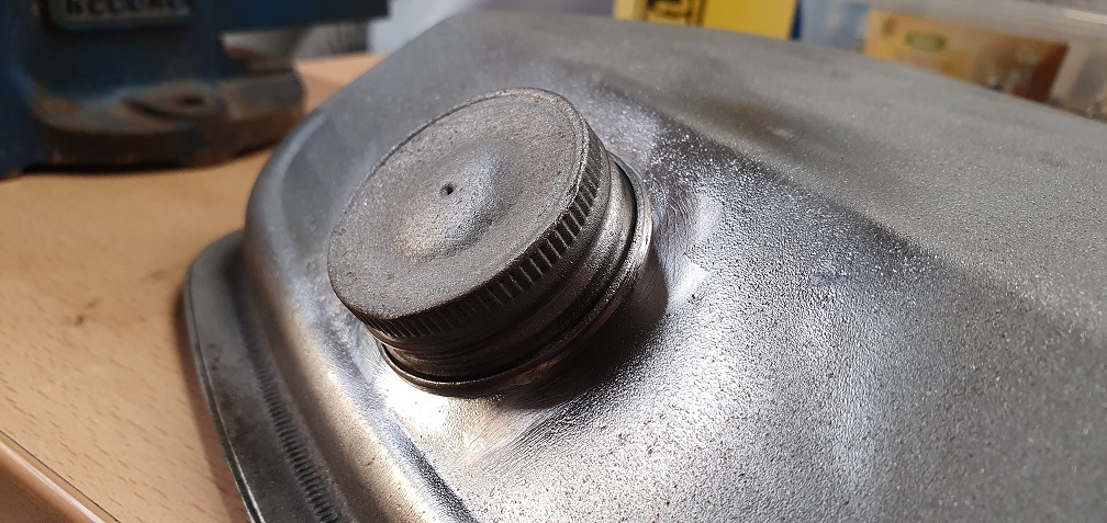
Meanwhile, the petrol tank needed a little tidying up before painting. It shows what looks like a previous weld repair? So took the rather lumpy weld down smooth being careful not to go down too far and expose whatever it was repairing. Also straightened out the outer edge of the tank all the way around as it was a bit wavy here and there
I'm going to soon be painting
I'm going to soon be painting as and when the weather improves a bit, but not sure on colour choice for the following parts:
Bottom Blade - Black?
Tie Rod connecting left and right sideplates - Green?
Front Roller spindle - Green?
Rear Roller spindle - Green?
With the roller spindles, I'm not sure if the paint will interfere with the fit, but presumably they would have been painted originally to protect from rust so there should be clearance for a layer or 2 of paint - hopefully...
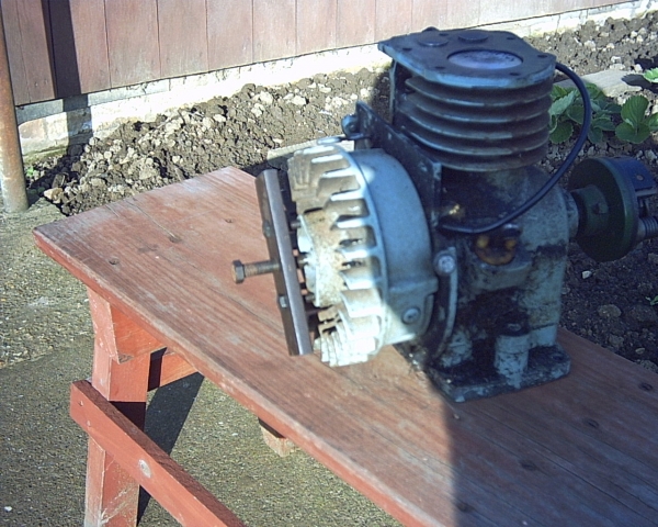
After spending much time
After spending much time ploughing a furlough working in the home garden...yesterday the dank drizzle sent me inside...I lifted the covers over my mower bench...under them is an Atco 12"....and a huge mouses nest....
I reckon it could be 12 years since I last worked on it...!!
Like yours it has almost every known "Super Colt" fault/wear/damage. It is 6 years since I gave it a mention on a forum!....where do the years go.?!
The stage it got to was chassis assembly, with cylinder painted and ground, a new bottom blade, throw plate painted and a bolt repair done to chain case side......then work and life stepped up a gear...
Repair criteria was and is...repair to best abilities as reqd to make it run and mow once more, leaving as original, except for serviced items... It had been retired from use by its original owner and arrived with me via a work colleague who had a habit of feeding my hobby of saving mowers from a trip to the tip.......it also had maybe five years in the old boiler house at work.!
Anyway, yesterday I made a few online purchases....to enable a potential restart of proceedings....
I won't make any promises..the sun may shine later and I could head outside........ ;)
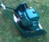
Here's a photo of the engine...photo seems to be dated 2011, when it was posing to demonstrate a flywheel puller....
C.
That was reasonably brave on
That was reasonably brave on the tank, did you use a power file?
I'm not too sure that was a repair, could have been original Friday knocking off splodge job.
Re paint, I would go with you on tie rods and bottom blade, but spindles... paint them by all means, at least anything on the ends will be in keeping, but hardly seen?
Clive, nice puller!
Why have the smileys been removed?
Clive - it was be great to
Clive - it would be great to see another similar machine up and running and to see some pictures as and when you have finished. I'd like to see one in it's 'work clothes' as such, if you do find time to bring it back to life!
Chris - I used a hand file to start with and then some small brass wire brush attachments on the drill and just went slowly. I think you are probably right - given the condition of the rest of the tank, and clean metal all around, with no signs of damage/rust, I think the tank has always been like that - bit of a Friday factory effort - the pub was probably more tempting than doing a neat job of attaching the filler neck!
In between priming, rubbing
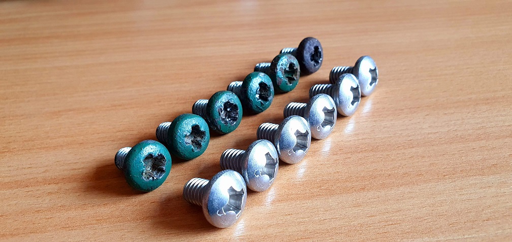
In between priming, rubbing down, removing small dents, spraying multiple coats of green, I'm looking at any other bits and pieces I need to order to replace any worn parts. The 6 main deck screws could do with being replaced as they are fairly rounded, and I remember struggling to remove a couple of them due to this.
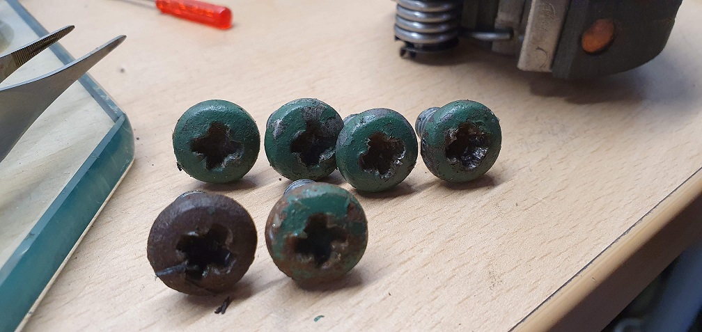
The original part number is L08592 which was replaced by part F016T40588. There are a few sources for these online, however I measured my current screws to double check sizing against the part numbers. They are 5/16-18 UNC x 1/2 inch Pan head machine screws. Ordered and on their way!
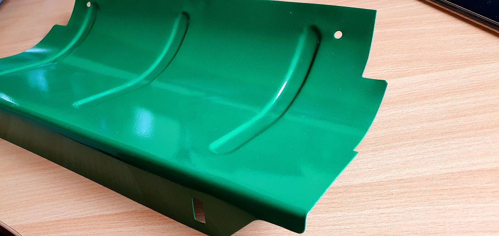
The grass deflector plate arrived and is in good condition with only minimal kinks to remove
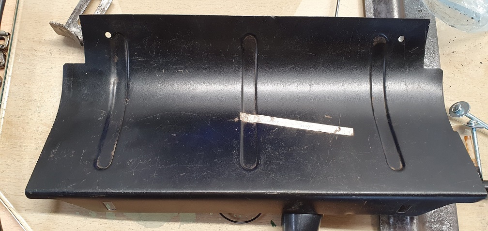
I'm not entirely sure of the reason for the 2 round holes near the lower edge of the plate - perhaps they will become clear when I reassemble - however other plates with the same part number do not seem to have these holes.
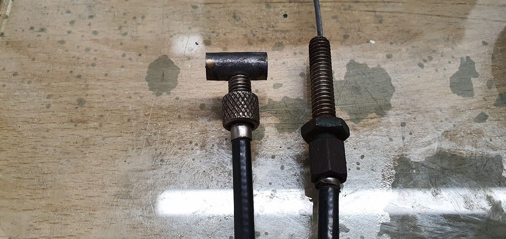
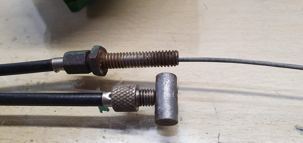
New throttle cable ordered as the old one was very rough. The clutch cable however is nice and smooth and just needs a clean up
Replacement screws arrived
Replacement screws arrived
Some painting pictures
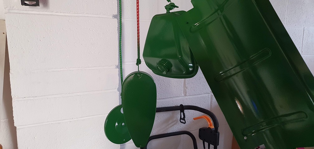
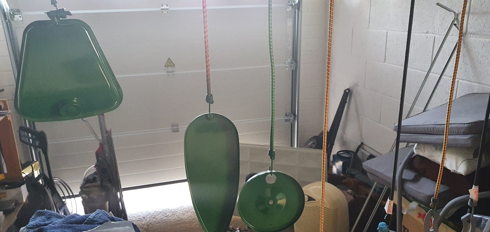
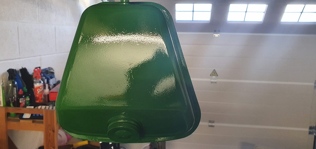
After the first coat I used some wet and dry of various grades in order to smooth out the paint a little to take away at least some of the rattle can look - especially on the petrol tank - pretty pleased with the results
Only a few bits left to do a final coat on now, but weather is halting play for the time being......
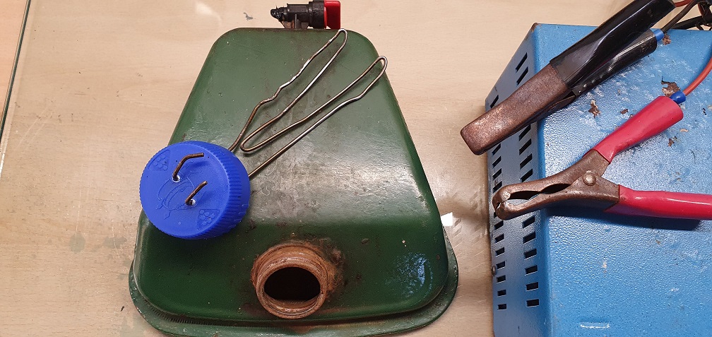
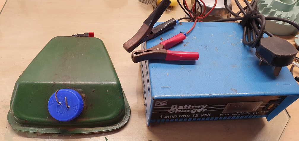
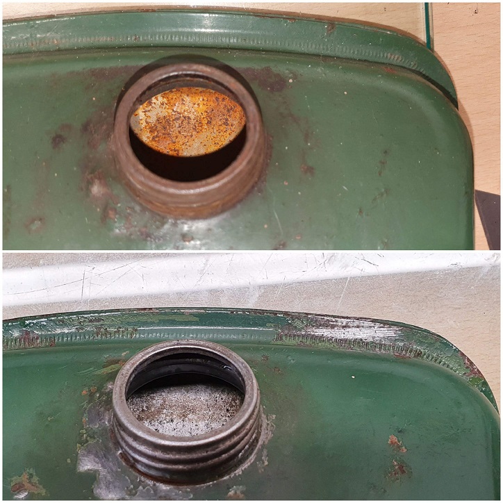
I'm looking for some help
I'm looking for some help identifying the correct thread size and petcock for my petrol tank. Pictures of the tank are below. It came to me with a broken black plastic petcock which had a red lever and looks like the more common newer style with a lever to turn. However, I believe that my mower would have used the plunger style petcock. Can anyone tell me what thread size this would have used please? I need to source a suitable bolt to plug the thread with so that I can carry out my de-rusting of the inside of the tank, and also I need to source a replacement petcock of the correct type and thread.
I'm planning on agitating the insides with some nuts and bolts and letting it sit with white vinegar in for a few days, and if this doesn't remove the rust sufficiently, i'll give some electrolysis a try.